.jpg)

.jpg)


Đối tác


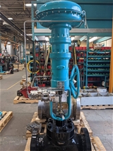
CONTROL VALVES - PCV
Mã sản phẩm: PCV-003
Giá bán: 0 ₫
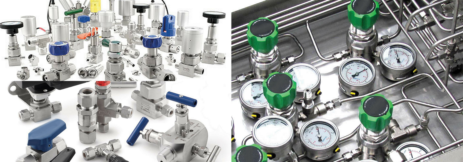
Control valves
A control valve is a valve used to control fluid flow by varying the size of the flow passage as directed by a signal from a controller. This enables the direct control of flow rate and the consequential control of process quantities such as pressure, temperature, and liquid level.
In automatic control terminology, a control valve is termed a "final control element".
Operation

Air-actuated control valves each with a 4-20 mA "I to P" converter integral to a valve positioner. In this example each positioner is comparing the valve stem travel against control signal, and applying any correction.
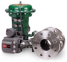
The opening or closing of automatic control valves is usually done by electrical, hydraulic or pneumatic actuators. Normally with a modulating valve, which can be set to any position between fully open and fully closed, valve positioners are used to ensure the valve attains the desired degree of opening.
Air-actuated valves are commonly used because of their simplicity, as they only require a compressed air supply, whereas electrically-operated valves require additional cabling and switch gear, and hydraulically-actuated valves required high pressure supply and return lines for the hydraulic fluid.
The pneumatic control signals are traditionally based on a pressure range of 3-15psi (0.2-1.0 bar), or more commonly now, an electrical signal of 4-20mA for industry, or 0-10V for HVAC systems. Electrical control now often includes a "Smart" communication signal superimposed on the 4-20mA control current, such that the health and verification of the valve position can be signalled back to the controller. The HART, Fieldbus Foundation, and Profibus are the most common protocols.
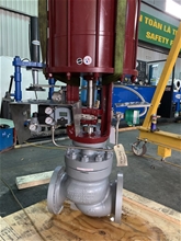
An automatic control valve consists of three main parts in which each part exist in several types and designs:
- Valve actuator - which moves the valve's modulating element, such as ball or butterfly.
- Valve positioner - Which ensures the valve has reached the desired degree of opening. This overcomes the problems of friction and wear.
- Valve body - in which the modulating element, a plug, globe, ball or butterfly, is contained.
Control action

Showing the evolution of analogue control loop signalling from the pneumatic era to the electronic era.

Example of current loops used for sensing and control transmission. Specific example of a smart valve positioner used.

Globe control valve with pneumatic diaphragm actuator and "smart" positioner which will also feed back to the controller the actual valve position
Taking the example of an air-operated valve, there are two control actions possible:
- "Air or current to open" - The flow restriction decreases with increased control signal value.
- "Air or current to close" - The flow restriction increases with increased control signal value.
There can also be failure to safety modes:
- Air or control signal failure to close" - On failure of compressed air to the actuator, the valve closes under spring pressure or by backup power.
- Air or control signal failure to open" - On failure of compressed air to actuator, the valve opens under spring pressure or by backup power.
The modes of failure operation are requirements of the failure to safety process control specification of the plant. In the case of cooling water it may be to fail open, and the case of delivering a chemical it may be to fail closed.
Valve positioners
The fundamental function of a positioner is to deliver pressurized air to the valve actuator, such that the position of the valve stem or shaft corresponds to the set point from the control system. Positioners are typically used when a valve requires throttling action. A positioner requires position feedback from the valve stem or shaft and delivers pneumatic pressure to the actuator to open and close the valve. The positioner must be mounted on or near the control valve assembly. There are three main categories of positioners, depending on the type of control signal, the diagnostic capability, and the communication protocol: pneumatic analog and digital.
Processing units may use pneumatic pressure signaling as the control set point to the control valves. Pressure is typically modulated between 20.7 to 103 kPa (3 to 15 psig) to move the valve from 0 to 100% position. In a common pneumatic positioner the position of the valve stem or shaft is compared with the position of a bellows that receives the pneumatic control signal. When the input signal increases, the bellows expands and moves a beam. The beam pivots about an input axis, which moves a flapper closer to the nozzle. The nozzle pressure increases, which increases the output pressure to the actuator through a pneumatic amplifier relay. The increased output pressure to the actuator causes the valve stem to move. Stem movement is fed back to the beam by means of a cam. As the cam rotates, the beam pivots about the feedback axis to move the flapper slightly away from the nozzle. The nozzle pressure decreases and reduces the output pressure to the actuator. Stem movement continues, backing the flapper away from the nozzle until equilibrium is reached. When the input signal decreases, the bellows contracts (aided by an internal range spring) and the beam pivots about the input axis to move the flapper away from the nozzle. Nozzle pressure decreases and the relay permits the release of diaphragm casing pressure to the atmosphere, which allows the actuator stem to move upward. Through the cam, stem movement is fed back to the beam to reposition the flapper closer to the nozzle. When equilibrium conditions are obtained, stem movement stops and the flapper is positioned to prevent any further decrease in actuator pressure.
The second type of positioner is an analog I/P positioner. Most modern processing units use a 4 to 20 mA DC signal to modulate the control valves. This introduces electronics into the positioner design and requires that the positioner convert the electronic current signal into a pneumatic pressure signal (current-to-pneumatic or I/P). In a typical analog I/P positioner, the converter receives a DC input signal and provides a proportional pneumatic output signal through a nozzle/flapper arrangement. The pneumatic output signal provides the input signal to the pneumatic positioner. Otherwise, the design is the same as the pneumatic positioner
While pneumatic positioners and analog I/P positioners provide basic valve position control, digital valve controllers add another dimension to positioner capabilities. This type of positioner is a microprocessor-based instrument. The microprocessor enables diagnostics and two-way communication to simplify setup and troubleshooting.
In a typical digital valve controller, the control signal is read by the microprocessor, processed by a digital algorithm, and converted into a drive current signal to the I/P converter. The microprocessor performs the position control algorithm rather than a mechanical beam, cam, and flapper assembly. As the control signal increases, the drive signal to the I/P converter increases, increasing the output pressure from the I/P converter. This pressure is routed to a pneumatic amplifier relay and provides two output pressures to the actuator. With increasing control signal, one output pressure always increases and the other output pressure decreases
Double-acting actuators use both outputs, whereas single-acting actuators use only one output. The changing output pressure causes the actuator stem or shaft to move. Valve position is fed back to the microprocessor. The stem continues to move until the correct position is attained. At this point, the microprocessor stabilizes the drive signal to the I/P converter until equilibrium is obtained.
In addition to the function of controlling the position of the valve, a digital valve controller has two additional capabilities: diagnostics and two-way digital communication.
Widely used communication protocols include HART, FOUNDATION fieldbus, and PROFIBUS.
Advantages of placing a smart positioner on a control valve:
1. Automatic calibration and configuration of positioner. 2. Real time diagnostics. 3. Reduced cost of loop commissioning, including installation and calibration. 4. Use of diagnostics to maintain loop performance levels. 5. Improved process control accuracy that reduces process variability.
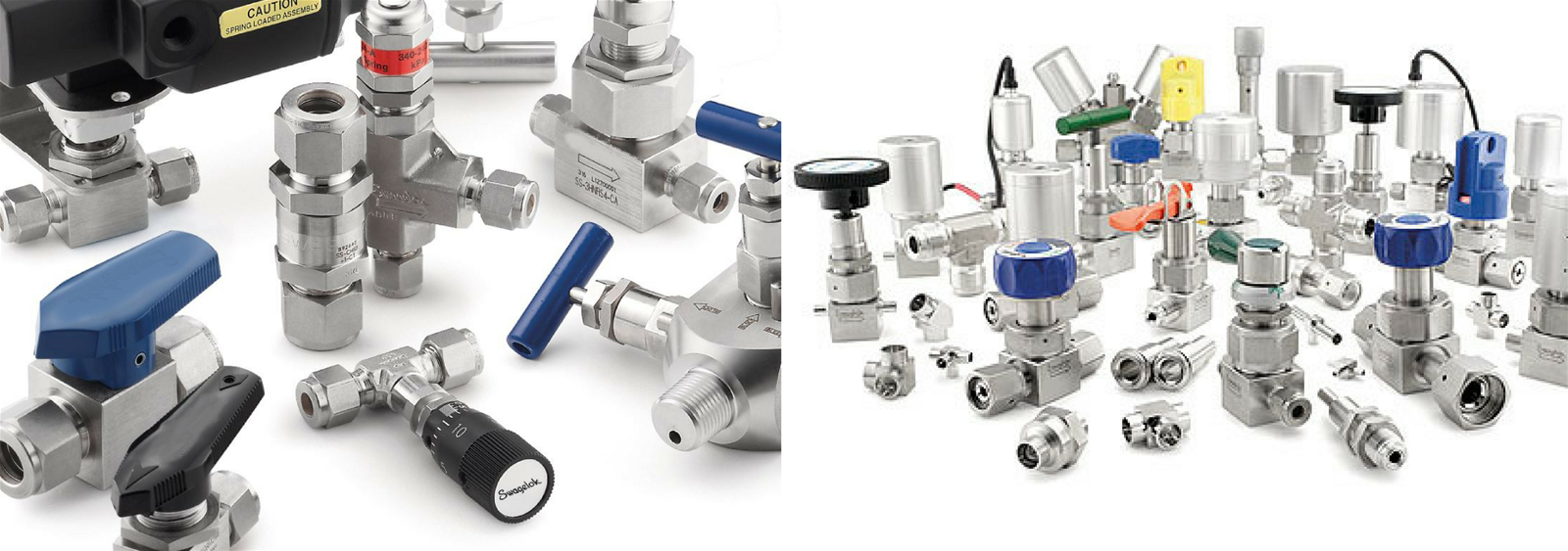
Types of control valve bodies
A huge variety of valve types and control operation exist. However, there are two main forms of action; the sliding stem and the rotary action.
The most common and versatile types of control valves are sliding-stem globe, V-notch ball, butterfly and angle types. Their popularity derives from rugged construction and the many options available that make them suitable for a variety of process applications. Control valve bodies may be categorized as below:
List of common types of control valve:
- Sliding Stem
- Rotary
- Other
Sản phẩm đã được thêm vào giỏ hàng
Sản phẩm đã được thêm vào giỏ hàng
Cảm ơn bạn đã quan tâm. Chúng tôi sẽ liên hệ lại với bạn trong thời gian sớm nhất.
Cảm ơn bạn đã quan tâm. Chúng tôi sẽ gửi những thông tin mới nhất của chúng tôi cho bạn qua email này!
Gửi phản hồi